Showing posts with label Embedded System. Show all posts

November 04, 2016

U-Boot | How to add a new command to u-boot console?

U-boot comes with a lot of stock commands which one can run on the u-boot console similar to the Linux console commands like 'ls'. The source for every command can be found under 'common/' directory with file names starting with 'cmd_'. However, not all commands are enabled by default.

A user may either want to enable a command the stock or add his/her own command. Both are possible in just few simple steps.

Note: You can check the list of commands already enabled from the commands list from the u-boot console by running the command 'help' or simply '?'.

1. Enabling a command from the stock
From the code, you can open 'common/Makefile' and under the '# command' section you can find the list of all the commands masked with config flags 'CONFIG_*'. To enable a command, you have to simply #define the corresponding flag under the 'include/configs/<board>.h' file and build the source. Now, you can see the command in the list of commands by running 'help'.

Example:
To enable a command 'source', in the 'common/Makefile', you can find
obj-$(CONFIG_CMD_SOURCE) += cmd_source.o

Simply include the corresponding flag in 'include/configs/<board>.h' file as follows
#define CONFIG_CMD_SOURCE

or in another ways, simply replace $(CONFIG_CMD_SOURCE) with 'y' as follows.
obj-y += cmd_source.o
will enable the command irrespective of any flags defined. However, the first method is most reliable and controllable from the board.h config file.

2. Adding and enabling a new command of your own
In this case, there are three things to be done.
  • Write an API(function) that implements your command.
  • Register your function to the command list.
  • Enable your command.
Write an API that implements your command: First thing is to write an API that implements your expected functionality. But, the API should follow a fixed prototype.

/* Prototype */
int do_funcname(cmd_tbl_t *cmdtp, int flag, int argc, char *const argv[]) 
where,
*cmdtp - Command table pointer (comparable to function vector table)
flag - Unused
argc - Argument count, including command name itself
argv[] -  Array of arguments (string)

Register your API to the command table: Registering your command to the command table is necessary for both, listed and command-line arguments to be properly passed to your API.
U-Boot provides the following prototype to register your API.

/* Prototype */
U_BOOT_CMD(_name, _maxargs, _rep, _cmd, _usage, _help)
where,
_name - Command Name (the name you want to run the command)
_maxargs - Maximum number of arguments
_rep - Autorepeat allowed? (0-No/1-Yes)
_cmd - Implementation function (pointer to your API)
_usage - Usage - Short help message (string)
_help - Long help message (string)

Note: Both the above prototypes are available in 'include/command.h' and hence need to include 'command.h' to your command file header.

Enable your command: Finally, all set to have your own command except one last thing, enabling them. For that, you have to follow the same method as the first case as follow.
obj-y += <filename>.o
or have a new flag defined, say CONFIG_CMD_FILENAME and
obj-$(CONFIG_CMD_FILENAME) += <filename>.o

Reference:
1. doc/README.commands in u-boot source.
2. xillybus.com

June 01, 2016

What is a device tree blob? Why is it needed?

Since the time when a number of ARM sub-architectures are entering the ground, it's been a big headache to the maintainers of the Linux source as there were huge number of duplicates to support specific sub-architecture and board configurations making the Linux Mainline so big and clumsy. To avoid this, the team came up with an idea to keep the board specific files away from the Kernel mainline and thus the birth of Device Tree Source (.dts) files which will be compiled as separate binary, Device Tree Blob (.dtb). With device tree, it is possible to use a single kernel image on different boards using the same SoC by simply passing a different device tree containing board specific data structure.. When booting, it is the boot-loader which passes this device tree to the kernel. At present, it is made mandatory to have Device Tree. More story about device tree can be found at xillybus.com, elinux.org, freebsd.org and more. Also check this document.

May 27, 2016

ARM Bare Metal Programming with GNU

ARM bare metal programming was considered a dark art and known only to very few. Here are the links that opens it to you on how to write a startup code, linker script and all that is hidden behind your popular IDEs. With this knowledge, you can start to write your code without the help of any IDEs. You can completely take in control where to place each of your bits on the RAM. Enjoy exploring the core of embedded programming.

Embedded programming with the GNU toolchain - bravegnu.org
Building Bare-Metal ARM Systems with GNU - embedded.com
Building Bare-Metal ARM Systems with GNU - mikrocontroller.net

May 17, 2016

Articles on 'const' and 'volatile' qualifiers

More recently I went through some of the articles and lectures on C and C++ by Dan Saks, a consultant in US. I especially liked his lecture on 'const' qualifier which was more thought provoking and felt, a must share article. http://www.dansaks.com/articles.htm. Also, he is a columnist at embedded.com

March 18, 2016

Bringing Wi-Fi Access Point Feature on your embedded board running GNU/Linux

Before reading through this article, to build and install GNU/Linux on embedded board, read through this link.

To bring WiFi client feature on your embedded board, read through this link.
----

Follow these simple steps below to bring your board as AP.
  1. Install necessary tools
    Install hostapd and dnsmasq necessary for an Access Point.
    # apt-get install hostapd dnsmasq --no-install-recommends
  2. Configure network interface
    Add or modify /etc/network/interface to contain the following.
    # cat /etc/network/interface
    auto lo wlan0
    iface lo inet loopback
    allow-hotplug eth0
    iface eth0 inet dhcp
    
    iface wlan0 inet static
    address 192.168.1.1
    network 192.168.1.0
    netmask 255.255.255.0
    allow-hotplug wlan0
    The above file says how our system get connected through eth0, wlan0 and lo. Check man page of interfaces for more details.
  3. Configure hostapd
    # cat /etc/default/hostapd
    DAEMON_CONF="/etc/hostapd/hostapd.conf"
    DAEMON_OPTS="-dd"
    # cat /etc/hostapd/hostapd.conf
    interface=wlan0
    driver=nl80211
    ssid=zilogic
    channel=1
  4. Configure dnsmasq with Client IP range
    # cat /etc/dnsmasq.conf
    
    interface=wlan0
    dhcp-range=192.168.1.10,192.168.1.100,12h
    dhcp-option=3,192.168.1.1
  5. Start hostapd and dnsmasq services.
    # service hostapd start
    # service dnsmasq start

Note: Now, you can try Raspberry Pi 3 that comes with WiFi and Bluetooth on-board for IoT applications.

More Reading

  1. What is the significance of firmware-atheros package?
  2. What is the significance of wireless-tools utility?
  3. What is iw and iwconfig? How do they differ?
  4. What is wpa_supplicant? How to connect to an encrypted connection?
  5. What is Wireless Extensions(WE)?
  6. What are nl80211 and cfg80211 and how do they differ from WE?
  7. What is Bridging in network connections? 

Bringing Wi-Fi Client Feature on your Embedded board running GNU/Linux

To prepare your embedded board with GNU/Linux running on it, read through this link.

To bring Wi-Fi  Access Point feature, read through this link.
----

To bring Wi-Fi client feature with the given NIC on your Embedded board running Linux, we may need
  1. Device driver for the given NIC enabled in the Kernel.
  2. Some HAL layer firmware, if required by the device driver. (Ref. ath9k_htc firmware - github.com)
  3. Certain utilities to configure and manage Wi-Fi.
    (iw, ip, iwconfig, wpa_passphrase, wpa_supplicant, firmware-atheros)

Installing custom packages

You may require some software utilities like, iwconfig, iw, etc., which may be required to solve your purpose. To install them there are the following possibilities.
  1. Download .deb packages of required utilities to a USB Stick or to the SD Card and install them using dpkg with -i option. But, we have to know all the dependencies for evey package you install and have them downloaded and installed prior to installing the main package.
  2. Include the packages while building the rootfs.
  3. Connect to internet through any possible interface available (ethernet, wlan) and using apt-get install them from your favorite repository. But, your board should have any such interface enabled and available for use.
  4. Use chroot on your host Linux System to change from the host’s rootfs to the SD Cards rootfs/(target fs). This method is followed in this case.

Installing custom packages using chroot

  • This requires super user access. VirtualBox together with Vagrant can be used to get super user access by normal user.
  • Also, chroot will work only if the target architecture is same as that of the host.
    1. When configuring kernel during compilation, enable support for ath9k_htc under device drivers in menuconfig. ath9k_htc is a device driver specific to atheros AR9271 which is the chipset used in our given NIC (TP-Link TL-WN722N).
    2. qemu-arm-static is a binary that can be installed in host and copied to target file system. This is used as an interpreter to run arm binaries of target file system(SD Card rootfs/). This will fix the architecture issue while using chroot.
      $ sudo apt-get install binfmt-support qemu-user-static
      $ cp /usr/bin/qemu-arm-static /home/user/rootfs/usr/bin
      Here, SD Card is mounted at /home/user/. The option binfmt-support says the binfmt_misc kernel module to use qemu-arm-static as the interpreter to execute arm binaries.
    3. Mount proc/ and sys/
      $ cd rootfs
      $ sudo mount -t proc none proc/
      $ sudo mount -t sysfs sysfs sys/
      $ sudo mount -o bind /dev dev/
    4. Change rootfs (need to be super user to do this)
      $ sudo chroot rootfs/
      root@emdebian:/#
    5. Update list and install packages (firmware-atheros, wireless-tools, wpasupplicant, wireless-tools, iw, kmod) and then exit and unmount proc, sys and dev. firmware-atheros is required for our case but not mandatory for all the atheros devices[3].
      # apt-get update
      # apt-get install firmware-atheros wpasupplicant wireless-tools iw kmod
      # exit
      $ unmount /rootfs/proc/
      $ unmount /rootfs/sys/
      Unmount the SD Card from the PC and connect to the board and boot it. In SAMA5D3_Xplained board, a dedicated DEBUG console is provided which can be used to connect to system terminal through a USB-Serial converter. After the system boots up and logged in, plug the NIC in the USB port. The device should be automatically detected and will be ready to use.
    6. Enable wlan0
      # ifconfig           /* To check if wlan inteface is listed */
      # ifconfig wlan0 up
      The second command will enable the default WLAN interface wlan0. Now the interface will be up and ready to use.

Connecting to an open network as Client

  1. Connecting to an open network is simple. It can be achieved using the iwconfig utility.
    # iwconfig dev wlan0 connect <SSID>
    You can also try iw.
  2. Get IP assigned from AP
    # dhclient wlan0
    You can check -r option for dhclient to release the current IP lease when necessary.

More Reading

  1. What is the significance of firmware-atheros package?
  2. What is the significance of wireless-tools utility?
  3. What is iw and iwconfig? How do they differ?
  4. What is wpa_supplicant[4]? How to connect to an encrypted connection?
  5. What is Wireless Extensions(WE)?
  6. What are nl80211 and cfg80211 and how do they differ from WE?
  7. What is Bridging in network connections?

Build and Install Linux for ARM Cortex-A5 based embedded board

For this present article, we use SAMA5d3_Xplained board based on ATSAMA5D36 (ARM based MPU). But, the same step follows for any other hardware.

This article aims to introduce on bringing up SAMA5D3_Xplained board as a Linux System.

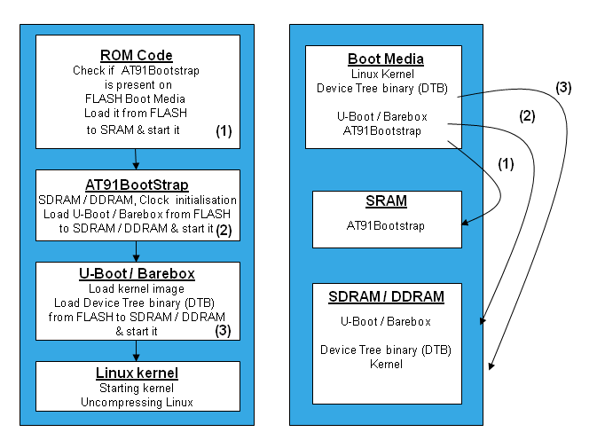
Before we start, we need to understand the boot sequence to know what should be done (Ref. Getting Started - at91.com)

Boot Sequence - at91.com
Boot Sequence (Source: at91.com)
The above image will show you three levels of bootloaders which are optional based on whether we implement simple firmware or OS.

Step:1 Prepare the necessary objects
  1. Bootstrap image
  2. Kernel Image
  3. Kernel modules
  4. Device tree file
  5. Rootfs Image 

Note:
arm-linux-gnueabi- toolchain required to build the image, can be downloaded form release.linaro.org and add path to gcc-linaro_<version>_arm-linux-gnueabi/bin directory.

$ export PATH=~/gcc-linaro-4.9-2014.11-x86_64_arm-linux-gnueabi/bin/:$PATH

To permanently add the path to the environment, add the above command to .bashrc file.

Building Bootstrap Image

  1. Clone/Download at91bootstrap source from linux4sam/at91bootstrap git repository.
  2. Configure the source with the default configuration for SD Card boot. You can find a number of default configurations for different boot media at ./board/sama5d3xek/ directory.
    $ cd at91bootstrap/
    $ make mrproper
    $ make sama5d3_xplainedsd_linux_image_dt_defconfig 
    Note:
    nf- NandFlash, sd - MMC Card, df - SerialFlash, linux - linux kernel, android - android kernel, uboot - u-boot, dt - device tree binary (dtb). (Ref. AT91Bootstrap - at91.com)

  3. Compile the at91bootstrap
    $ make CROSS_COMPILE=arm-linux-gnueabi-
    The resulting binary will be created at ./binaries/ with the name sama5d3_xplained……bin .

Building Kernel Image, Device Tree (.dtb) and Kernel Modules

The Kernel Image, Device Tree Binary and Kernel Modules are all built form Kernel Source with different options.
  1. Get Kernel Source either from kernel.org or linux4sam/linux-ar91 git repository.
  2. Configure the build with default configuration.
    $ cd linux-at91
    $ make ARCH=arm CROSS_COMPILE=arm-linux-gnueabi- sama5_defconfig
    Note: More default configurations for various standard boards can be found at arch/arm/configs/. Equivalently, you can also copy the desired configuration file from this directory to root directory with file name '.config' and run make defconfig.
  3. For any changes needed in the configuration, configure using menuconfig
    $ make ARCH=arm CROSS_COMPILE=arm-linux-gnueabi- menuconfig
  4. Compile for Kernel Image
    $ make ARCH=arm CROSS_COMPILE=arm-linux-gnueabi- zImage
  5. Compile for Device Tree Binary(.dtb)
    $ make ARCH=arm CROSS_COMPILE=arm-linux-gnueabi- dtbs
  6. Compile for Kernel Modules
    $ make ARCH=arm CROSS_COMPILE=arm-linux-gnueabi- modules
    The images will be created at arch/arm/boot/.

Building Rootfs

There are several Roofs build systems available such as Yocto, Buildroot, Busybox, Multistrap, etc.,
For our convenience, we can get the archived pre-built custom Rootfs from shark/zdrive. Other sources can also be found online(sborut.wordpress.com, Dropbox). But, for ARM architecture.

Preparing SD/MMC Card

In SD Card, two partitions are to be created.
  • First partition (FAT32) ⇒ boot/ ⇒ required to move the boot images(bootstrap, kernel image and device tree binary).
  • Second partition (EXT4) ⇒ rootfs/ ⇒ for the root file system requied by the kernel to run.
Note:
fdisks is a command-line tool for creating and managing partitions. mkfs is another command-line tool to format paritions to required file system. Need to be super user to use this tool.
  1. After the SD Card is ready with the required partitions say by name, boot and rootfs, copy the bootstrap image, kernel image, dtb to boot/ as follows.
    $ at91bootstrap/binaries/sama5d3_xplained-sdcardboot-linux-image-dt-3.8.bin  /media/user/boot/boot.bin
    $ cp linux-at91/arch/arm/boot/zImage /media/user/boot/image
    $ cp linux-at91/arch/arm/boot/dts/at91-sama5d3_xplained.dtb /media/user/boot/
  2. Untar the downloaded rootfs archive to the second partition rootfs
    $ tar -xvf  rootfs-armel-wheezy.tar.xz -c /media/user/rootfs
  3. Install the Kernel Modules into rootfs
    ~/linux-at91 $ make modules_install ARCH=arm CROSS_COMPILE=arm-linux-gnueabi- INSTALL_MOD_PATH=/media/user/rootfs
    Now, your SD Card is ready with the necessary components to run Linux on SAMA5D3 Xplained board.

Bringing Wi-Fi Client Feature

To bring Wi-Fi client feature with the given NIC, we may need
  1. Device driver for the given NIC enabled in the Kernel.
  2. Some HAL layer firmware, if required by the device driver. (Ref. ath9k_htc firmware - github.com)
  3. Certain utilities to configure and manage Wi-Fi.
    (iw, ip, iwconfig, wpa_passphrase, wpa_supplicant, firmware-atheros)
  4. Read on through this link to bring WiFi Client feature.

January 30, 2016

Steps to configure NuttX to run a built-in app from NuttX Command Line (Nutt SHell or NSH)

For people who are new to NuttX like me, in a sentence, NuttX is an embedded RTOS. You can read the overview at nuttx.org. If you have tried building NuttX for your favorite board with the example application or your own application, you may be looking to run your application concurrently from NSH (Nutt SHell) as like we do in GNU/Linux Command line. Bringing up such feature is by enabling Built-In application. The following explanation is a digest of my learning from 'NuttX/apps/README.txt' and acassis blog post.

  1. To enable built-in app to be available in nsh, edit 'nuttx/configs/<board_name>/nsh/defconfig' and add the below configurations
    CONFIG_BUILTIN=y
    CONFIG_NSH_BUILTIN_APPS=y
    
    CONFIG_EXAMPLES_MYAPP=y /* To allow configuring myapp as
                               built-in app */
  2. fork 'apps/examples/hello' to 'apps/examples/myapp' and

    1. rename 'myapp/hello_main.c' to 'myapp/myapp.c'
       
    2. Edit 'myapp/mayapp.c' and change 'hello_main()' to 'myapp_main()'
       
    3. modify 'myapp/Kconfig' to resemble the following code to reflect your application name

      config EXAMPLES_MYAPP
              bool "\"Myapp Hello, World!\" example"
              default n
              ---help---
                      Enable the \"Myapp Hello, World!\" example
      
      if EXAMPLES_MYAPP
      
      config EXAMPLES_MYAPP_PROGNAME
              string "Myapp Program name"
              default "myapp"
              depends on BUILD_KERNEL
              ---help---
                      This is the name of the program that will be
                      use when the NSH ELF program is installed.
      
      endif
    4. modify 'myapp/Makefile' with the following to reflect your application name.

      APPNAME         = myapp
      CSRCS           = myapp.c

      Note: The 'APPNAME' above should reflect the prefix in myapp_main() and this is the same name by which your NSH command line app will be.
    5. modify 'myapp/Make.defs' to reflect the following code

      ifeq ($(CONFIG_EXAMPLES_MYAPP),y)
              CONFIGURED_APPS += examples/myapp
      endif
      • check 'apps/examples/Make.defs' for

        include $(wildcard examples/*/Make.defs)
        if its not present, add it. This makes 'Make.defs' file in every examples subdirectory to be added when configuring. (In otherways, the 'myapp/Make.defs' can be omitted and its contents can be copied to this 'Make.defs' file.)
  3. In 'apps/examples/Kconfig' file, include

    source "$APPSDIR/examples/myapp/Kconfig"
  4. fork 'nuttx/configs/hello' to 'nuttx/configs/myapp' and modify 'myapp/defconfig' to add

    CONFIG_EXAMPLES_MYAPP=y
    and comment all other examples if enabled. Say,
    # CONFIG_EXAMPLES_HELLO is not set
  5. At this point, everything is set and ready if you are not using any hardware peripheral such as UART, SPI, I2C, CAN, etc. You can jump to the next step. If you are accessing any hardware peripheral, then you need to set the corresponding configuration macros as true. You can do that in 'nuttx/config/<board_name>/myapp/defconfig'
     
  6. In terminal, go to 'nuttx/tools' and run the following command to tell the Makefile to use 'nsh' example.

    $ ./configure.sh <board_name>/nsh
  7. Switch back to 'nuttx' directory and run 'make' but with the parameters as below to choose the required toolchain.

    $ make CONFIG_ARMV7M_TOOLCHAIN_CODESOURCERYL=y
           CONFIG_ARMV7M_TOOLCHAIN_BUILDROOT=n 
After building and dumping the code, in nsh, using the command 'help'will list the available built-in app by the name as you provided for the 'APPNAME' macro in the Makefile.

December 26, 2015

CC3200 Launchpad UART Interrupt handling

For enabling and using UART in CC3200 using SDK without interrupt, visit CC3200 Launchpad - Enabling UART.

If you are having problem with simple UART transaction, please go through the above mentioned post and come back to learn interrupt handling.

There are only a very few more steps to enable and using Interrupt handler for UART. This should be considered as continuation of the above mentioned post.

All the APIs below are prefixe 'MAP_'. But, it can also be used without the prefix. But, prefix is recommended to reduce the size of the binary by mapping the APIs pre-written on the internal ROM chip.

//To enable the Global Interrupt
MAP_IntEnable(FAULT_SYSTICK);

Enabling the global interrupt will make all the unmasked peripheral interrupt to be visible to the interrupt controller.

//Registers a handler for UART1 interrupt                                  
MAP_UARTIntRegister(UARTA1_BASE, UART1_IntHandler);

Registers the interrupt handler with the name given by the second parameter for the UART1. The interrupt handler shall contain the ISR to be run on occurrence of the interrupt.
//Enables interrupt for UART1
MAP_UARTIntEnable(UARTA1_BASE, UART_INT_RX | UART_INT_RT);

The above API unmasks the individual UART interrupts as given by the second parameter. The second parameter can be OR'd value of any or all possible interrupt sources. Here, the macro UART_INT_RX refers to the interrupt on reception of a data at the RX register. UART_INT_RT refers to the Receive timeout interrupt which occurs after pre-defined timeout after the reception of data. Transmit interrupt can also be enabled by OR'ing UART_INT_TX macro. The TIs CC3200 comes with 8 byte Transmit and Receive FIFO to help buffering of serially sent or received data. It also can help reduce the frequency of interrupt.

The Interrupt handler should use the same name as registered with UARTIntRegister as follows.

//Interrupt handler
void UART1_IntHandler() {
  unsigned char ch;

  while((ch = MAP_UARTCharGetNonBlocking(UARTA1_BASE) != -1) {
    chararray[i++] = ch;
  }

}

CC3200 Launchpad SimpleLink enabling UART

The below tutorial to enable and use UART is by using the CC3200 SDK library version 1.1.0 but it will be compatible with other versions as well.

First let me list the library header files that are required for this program.
Considering UART1
  1. rom_map.h
  2. hw_memmap.h
  3. prcm.h/prcm.c
  4. pin.h/pin.c
  5. uart.h/uart.c
  6. uart_hal.h/uart_hal.c

//Enable the UART peripheral clock
MAP_PRCMPeripheralClkEnable(PRCM_UARTA1, PRCM_RUN_MODE_CLK);

//Pin Configuration
// Configure PIN_01 (GPIO_10) for UART1_TX                   
MAP_PinTypeUART(PIN_01, PIN_MODE_7);
// Configure PIN_02 (GPIO_11) for UART1_RX
MAP_PinTypeUART(PIN_02, PIN_MODE_7);

//Set the UART1 Configurations (Clock, Baudrate, Data, Stop and Parity bits)
MAP_UARTConfigSetExpClk(CONSOLE,MAP_PRCMPeripheralClockGet(CONSOLE_PERIPH), UART_BAUD_RATE, (UART_CONFIG_WLEN_8 | UART_CONFIG_STOP_ONE | UART_CONFIG_PAR_NONE));

Now, the UART1 is configured to work with GPIO pins 10 (TX) and 11 (RX) with baud rate as defined by the macro UART_BAUD_RATE and data length of 8 bits, 1 stop bit and no parity check. You can also choose different pin sets such as GPIO_16 as TX and GPIO_17 as RX or any other pin sets as defined in the technical reference manual.

Lets look at APIs to send and receive data. There are API defined to send and receive data both in non-blocking and blocking (polling) methods.

Blocking Codes - Waits for data reception or transmission completion by entering a conditional loop and blocking the cpu.

Non-Blocking Codes - Looks for data, data is retrieved if available or else, it continues executing the next instruction.

//Blocking codes

//Receive data
Data = UARTCharGet(UARTA1_BASE);

//Send data
UARTCharPut(UARTA1_BASE, Data);

//Non-Blocking codes

//Receive data
Data = UARTCharGetNonBlocking(UART1_BASE);

//Send data
UARTCharPutNonBlocking(UARTA1_BASE, Data);

Here, UART1_BASE is a macro defining the base memory location of UART1 as given in memory map in the Datasheet and is defined in hw_memmap.h. The variable 'Data' is the data received or sent. By using the UARTCharGet or UARTCharPut API inside a loop a string of data can be sent over serial port.

In the SDK, there are functions prefixed with 'MAP_' which are macros defined in rom_map.h which actually maps to the memory location of internal ROM where these APIs are pre-written as part of the servicepack. This reduces the size of binary file and serial flash utilization.

UART can also be used with interrupt enabled. For UART interrupt handling, visit CC3200 Launchpad - UART Interrupt handling.

November 24, 2015

Linux - Getting started with Texas Instruments CC3200 SimpleLink Launchpad IoT evaluation module

  • CC3200 has a FT2232 FTDI chip with USB to JTAG & UART (dual endpoints)
  • udev rules need to be added to enable FTDI chip to be visible in the file system
/etc/udev/rules.d/99-tiftdi.rules

$ cat /etc/udev/rules.d/99-tiftdi.rules
# For CC3200 Launchpad with FTDI Chip that TI put their codes in. ID = 0x0451, Product ID = 0xc32a
ATTRS{idVendor}=="0451", ATTRS{idProduct}=="c32a", MODE="0770", GROUP="dialout", RUN+="/sbin/modprobe ftdi-sio", RUN+="/bin/sh -c '/bin/echo 0451 c32a > /sys/bus/usb-serial/drivers/ftdi_sio/new_id'"
  • Necessary kernel modules are usbserial and ftdi_sio. We need to initiate ftdi_sio kernel module manual every time we connect the device. RUN+="/sbin/modprobe ftdi-sio" in the above rules does this automatically.
  • Though CCS studio is available for linux, arm-none-eabi-gcc toolchain can be used for compilation arm-none-eabi-gdb and openocd can be used for debugging.
  • energia, a opensource IDE for TI chips as like Arduino for Atmel chips. Energia can also be used as abstraction framework for other IDEs as well. Source: ​http://energia.nu/
  • energia is the easiest way to develop the project as it provides the highest level of abstraction with simple API for every feature.

October 10, 2015

ARM Programs for basic understanding

Below is some basic ARM program for the STM32L152 Discovery Board (Cortex M3) without using any programming library. Here, we directly configure the registers using self defined macros. This will help understand the hardware architecture as well. This is the method how libraries are built. But for fast programming, programming libraries such as CMSIS is recommended. Refer STM32L152 Datasheet for register memory-map (~Chapter 5).

1. Blink LED
2. Timer2 programming
3. USART1 programming
4. Automated Power Tiller - A project with ISR and modular code

Inter-Integrated Circuits(I2C)

Inter-Integrated circuits (I2C), a serial bus communication protocol using two lines; a serial data and a serial clock line. Developed by Philips for connecting low speed peripheral devices on computer board. It is one of the internationally accepted standards. Here is a presentation on the technical details of the bus protocol for download.

August 13, 2015

A complete course materials on embedded System design

This is a series of presentation from an Embedded System Course that covers the course content in total of 8 modules. Below is the link to all the modules. These presentations will suffice the basics to start with embedded system design.

  1. Embedded C and 8-bit Microcontroller
  2. System Design Using ARM
  3. Embedded Linux
  4. Embedded RTOS (VxWorks, RTLinux)
  5. System Design using DSP
  6. System Design using FPGAs

November 24, 2014

Centre for Development and Advanced Computing (C-DAC) - Education and Training programmes

C-DAC's Education and Training programmes are aimed at creating skilled manpower in the country by providing quality training programmes in the field of Electronics and ICT. This activity started almost two decades ago with a humble beginning of training about 20 students per year, but has today grown to an extent of training more than 5000 students per year. It also grew from just one training centre to about 50 training centres across India and has even made its presence in several countries abroad. In addition to conducting wide range of training programmes in the areas of Information, Communication and Electronics technologies, C-DAC also develops ICT tools and technologies for modern methods of imparting education and training to masses. The Education and Training activities of C-DAC are governed and steered by Academic Council (AC) and Academic Management Committee (AMC).
Presently, C-DAC offers its various training programmes through its own training centres in Bengaluru, Chennai, Hyderabad, Kolkata, Mohali, Mumbai, Noida, Pune and Thiruvananthapuram, and its network of Authorised Training Centres (ATC) spread across the country.
The various activities under the umbrella of C-DAC's Education and Training Programmes are described below:
Post Graduate Diploma Programmes
C-DAC conducts two batches of following PGD...
Go

Formal Training Programmes
C-DAC also conducts formal training programmes...

Go

Faculty Development Programmes
C-DAC conducts advanced faculty training programmes...


Go

Corporate Training Programmes
C-DAC offers various specialized training...
Go

Education Technologies
C-DAC has taken major initiatives in developing...
Go

Other Initiatives
Capacity Building Initiatives...

Go

International Training Program
International Training Program...
Go


November 13, 2014

NIELIT | Course Calendar 2015

http://calicut.nielit.in/course/calendarcedti.asp

Course Code Course Name Duration Starting Date Course Fee * Course Brochure
Information Technology Group
 SW100 PG Diploma in Software Technology  6 Month(s)   Mar-9-2015  67000 
    SW101 Diploma in .NET Technologies  3 Month(s)   Dec-8-2014  35100 
    SW102A Diploma in JEE  3 Month(s)   Mar-9-2015  35100 
    SW102B Diploma in Android Application Development  3 Month(s)   Mar-9-2015  35100 
 SW250 Diploma in PHP and jQuery  3 Month(s)   Feb-25-2015  30000 
 SW302 Diploma in .Net Technologies (Online Course)  3 Month(s)   Feb-25-2015  10000 
 SW304 Diploma in PHP Programming (Online Course)  3 Month(s)   Feb-25-2015  10000 
 SW500 PG Diploma in Information Security and Cloud Computing  24 Week(s)   Feb-25-2015  73000 


Embedded Systems Group
 ED500 PG Diploma in Embedded System Design  24 Week(s)   Feb-25-2015  80000 
 AED600 PG Diploma in Embedded Real Time Systems  24 Week(s)   Feb-25-2015  80000  -


Process Control and Instrumentation Group
 PC100 PG Diploma in Industrial Automation System Design  24 Week(s)   Mar-23-2015  80000 
 PC500 Advanced Diploma-PLC/SCADA/DCS Engineer  16 Week(s)   May-4-2015  40000 


VLSI Design Group
 US100 Diploma in Medical Ultrasound  200 Hour(s)   Mar-30-2015  25000 
 AVL500 PG Diploma in VLSI & Embedded Hardware Design  24 Week(s)   Feb-25-2015  80000  -
 AVL600 PG Diploma in ASIC Design and Verification  24 Week(s)   Mar-30-2015  80000  -


General Details:

Click on individual course codes for more details of the courses. Some courses are modular programs. The full course name is displayed in bold face. One can apply for total/individual modules. For PG Diploma courses, Diploma Students will be given only 'Advanced Diploma' certificate instead of PG Diploma.
Eligibility:
Engineers/Diploma/Graduates with appropriate experience. Please click on individual courses to see the eligibility details of that particular course. Final year students may also apply.
Hostel:
Hostel Facility is available for boys and girls on daily or monthly chargeable basis. However, students are required to pay the hostel fees for the duration of the course for which they are seeking admission at the time of joining the course. The hostel rent varies from Rs.850 to Rs.1400 per month depending on the location of the accommodation and facilities available. Caution deposit varies from Rs.300 to 1500 depending upon the duration of the stay, and the same is required to be paid in addition to the hostel rent.
Fees:
The students are normally required to pay the entire course fee at the time of admission. However, in the case of certain specified courses, the students can also make payment of fees in installments (applicable only for courses mentioned in the training calendar and are of duration 4 months or more). Service tax on the course fee will be charged extra at actuals. SC/ST/Physically Handicapped candidates are eligible for seat reservation for all the courses as per Govt. of India norms.
Tution Fees/Examination fees are waived for SC/ST students subject to terms and conditions. The students are requested to contact the Training Officer to know the fees payable by them for the Course Materials and other charges.

Intimation of Selection:
The students selected for the course/s shall be intimated of his selection by email/post/courier. The students are therefore required to provide their correct email address and are advised to check their email/visit our website to know about their selection. List of selected students shall also be available in our website (for select courses only).
How to Apply:
Students can apply for the course/s by either filling up the online application form or by downloading the application form and forwarding the same to the Training Officer, along with DD for Rs.1000/- as Advance Deposit.  For the admitted students, this advance deposit will be converted to caution deposit which will be refunded at the end of the course. This advance deposit will not be refunded for a selected candidate who does not join the course.

1. Procedure for Online application : Students can apply online by filling up the online application form. Click here to apply online. The students are first required to obtain the DD for Rs.1000/- towards Advance Deposit. The students are required to fill the details with regards to the DD Number, Date and amount. The students are requested to note down their registration number allotted after pressing the "Submit" button and forward the demand draft mentioning their name and their online registration number. Online registrations not containing the details with regards to the Advance Deposit details will not be considered for registration. If the payment is done through online banking or directly through bank, the original receipt/counterfoil of the same should reach here before the last date to apply.

2. Procedure for applying using the Application form : The students can download the application form from our web site (Download Application Form ) and fill the particulars and forward the same to the Training Officer along with the requisite fee as mentioned above.
3. Mode of  Payments : The course fee can be paid by one of the following methods

August 08, 2014

Microchip PIC Timer Tutorial

Concept of timer is clearly explained in the download below. Also, a clear differentiation between timer and counter is provided. Download (.pdf)

August 07, 2014

Embedded programming for LCD interfacing with microcontroller (ATMEL / PIC)


Embedded programming for LCD display Interfacing
(Book: The 8051 Microcontroller an Embedded Systems – using Assembly and C, Muhammad Ali Mazidi, Janice Gillispie Mazidi, Rolin D. McKinlay)
LCD Interfacing
Pin
Symbol
I/O
Description
1.   
Vss
-
Ground
2.   
Vcc
-
+5V power supply
3.   
VEE
-
Power supply to control contrast
4.   
RS
I
RS=0 – select command register
RS =1 – select data register
5.   
R/W
I
R/W=0 – Write
R/W=1 – Read
6.   
E
I/O
Enable
7.   
DB0-DB7
I/O
8-bit data bus

LCD Command Codes
Code
(Hex)
Command to LCD instruction register
1
Clear display screen
2
Return home
4
Decrement cursor (shift cursor to left)
6
Increment cursor (shift cursor to right)
5
Shift display right
7
Shift display left
8
Display off, cursor off
A
Display off, cursor on
C
Display on, cursor off
E
Display on, cursor blinking
F
Display on, cursor blinking
10
Shift cursor position to left
14
Shift cursor position to right
18
Shift the entire display to the left
1C
Shift the entire display to the right
80
Force cursor to beginning of 1st line
C0
Force cursor to beginning of 2nd line
38
2 lines and 5×7 matrix

Example Program:
To write/read on the LCD, first a set of commands (from above table) should be sent to the LCD module to set mode and clear display. Below is a set of functions in an order to make you understand easily.
(Don’t consider the item displayed, instead “HELLO!” will be displayed)


Receive all updates via Facebook. Just Click the Like Button Below

▼

You can also receive Free Email Updates:

dgpride - Study Zone - Free Books - Tamil Lyrics

Copyright © 2008 -2012 dgpride. All rights reserved.

Subject/Topics

2 Marks (26) 8051 (1) AC Machines (7) Animations (1) Anna University Chennai (31) Arduino (4) ARM (3) Audio (1) Basic C Concepts (8) Basic Electronics (13) Basic principles (9) Book list (1) CAD (1) Chemical (2) Circuit theory (6) Civil (2) Cloud Computing (1) Communication (4) Competitive exams (2) Computer Architecture (4) Control system and components (9) CSE (40) Curriculum (4) DC Machines (9) Did you know (14) Digital (13) DLC (4) Documentation (1) DSP (1) EC 2201 (3) ECE (45) EDC (1) EEE (34) EIE (63) Electrical (35) Electronics (43) Electroplating (2) Emacs (1) Embedded basics (19) Embedded C Programming (19) Embedded Linux (5) Embedded System (22) Engineering basics (15) Environmental Science (1) Fibre Optics (1) Filters (2) FPGA (1) GATE (3) General (7) GNU (4) Handwritten (1) Hobbyist (15) How to (8) HTML (3) Humanities (2) IC Engines (7) ICE (5) Industrial Electronics (10) Industrial Instrumentatin (2) industrial process (2) Instrumentation (21) IoT (2) IT (2) Laboratory Manuals (17) LabVIEW (2) Lesson notes (2) LIC (2) Links (9) Linux (8) Magnetics (1) Management (1) Mechanical (5) Mechatronics (9) Microcontrollers (14) Microprocessors (9) Microsoft (1) Motivation (1) Must Know (11) Networks (1) NuttX (1) Objective type (1) Open Source (1) Opportunities (7) Oscillators (2) Part Time (1) Physics (1) Post Graduation (1) Power Electronics (12) Power Plant Engineering (2) Power Supplies (2) Previous GATE Papers (1) Process Control (2) Project (4) Protocol (1) R2008 (11) R2009 (1) R2013 (1) Recruitment (2) Research (2) Robotics (9) RTOS (3) Signal Processing (8) Signals and Systems (4) SMPS (1) Software tutorial (4) Stepper Motor (2) Syllabus (5) Texas Instruments (2) Thermodynamics (2) Training and Placement (6) Transducer Engineering (2) Transformer (2) Transmission (1) Tutorials (48) Two Marks (26) U-Boot (1) University Question Papers (16) Verilog (1) Video (4) Virtual Instrumentation (3) Visual Basic (21) VLSI (11) Web designing (4) Wi-Fi (3) Wireless (6)